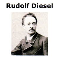
Educated at Munich Polytechnic, after graduating , he was employed as a Refrigerator Engineer by his Uncle.
1893 – at Augsburg, his model single 3.0M iron cylinder engine ran on its own power for the first time, the same year he obtained patent RP 67207 entitled “ Theory and Construction of a Rational Heat-engine to Replace the Steam Engine and combustion Engines Known)
1894 – He Published a Paper on an Engine with spontaneous combustion within the cylinder.
1896 – He demonstrated another improved model engine with a theoretical thermal efficiency of 75% while comparable Steam Engines were running at 10%
1898 – Diesel was granted U.S. patent 608,845 for an “internal combustion engine” By this time he had become a millionaire.
1913 – He vanished overboard from a steamer bound for London, his body was picked up 10 days later. Was it suicide or murder? We will never know!
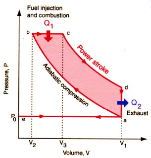
The Air Standard Diesel Engine Cycle
The Ideal air-standard cycle is modeled as :-
An Adiabatic compression – followed by a Constant Pressure combustion process. - Then an Adiabatic Expansion as a Power stroke – and finally an isovolumetric exhaust. – A new air charge is admitted at the end of the exhaust – as indicated by the process a-e-a on the diagram
In the diesel engine, only air is introduced into the combustion chamber. The air is then compressed with a compression ratio typically between 15 and 22 resulting in a 40 bar (about 600 psi) pressure compared to 14 bar (about 200 psi) in the petroleum engine. This high compression heats the air to 550 °C (about 1000 °F). At about this moment (the exact moment is determined by the fuel injection timing of the fuel system), fuel is injected directly into the compressed air in the combustion chamber. This is usually into a concave depression in the top of the piston or a 'pre-chamber‘ in small engines.
As well as the high level of compression allowing combustion to take place without a separate ignition system, a high compression ratio greatly increases the engine's efficiency.
Increasing the compression ratio in a spark-ignition engine where fuel and air are mixed before entry to the cylinder is limited by the need to prevent damaging pre-ignition. Since only air is compressed in a diesel engine, and fuel is not introduced into the cylinder until shortly before top dead centre (TDC), premature detonation is not an issue.
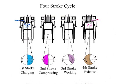
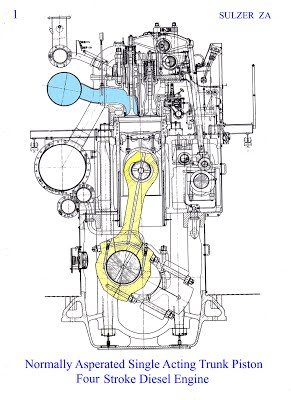
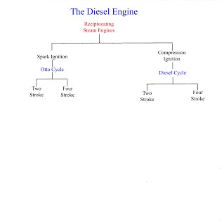
As with Otto Cycle engines, there are two classes of diesel engines in current use: two-stroke and four-stroke. The four-stroke is the "classic" version, tracing its lineage back to Rudolf Diesel's prototype. It is also the most commonly used form, being the preferred power source for many motor vehicles, especially buses and trucks.
Much larger engines, such as those used for railroad locomotion and marine propulsion, are often two-stroke units, offering a more favorable power-to-weight ratio, as well as better fuel economy. The most powerful engines in the world are two-stroke diesels of massive proportions.
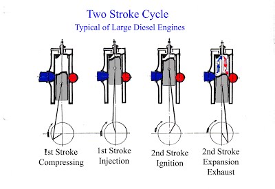
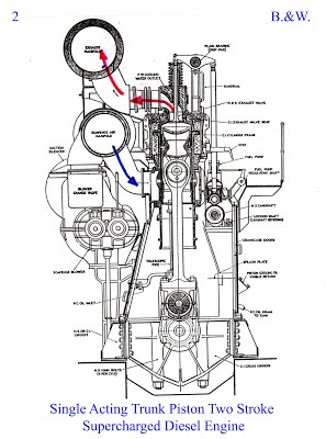
Two-stroke diesel operation is similar to that of the Otto Engine, except that fuel is not mixed with air prior to induction, and the crankcase does not take an active role in the cycle. The traditional two-stroke design relies upon a mechanically driven positive displacement blower to charge the cylinders with air prior to compression and ignition. The charging process also assists in expelling combustion gases remaining from the previous power stroke. (scavenging) In a two-stroke diesel engine, as the cylinder's piston approaches the bottom dead centre, exhaust ports or valves are opened relieving most of the excess pressure, after which, a passage between the air box and the cylinder is opened, permitting air flow into the cylinder.
The air flow blows the remaining combustion gases from the cylinder—this is the scavenging process. As the piston passes through bottom center and starts upward, the passage is closed and compression commences, culminating in fuel injection and ignition
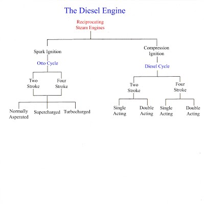
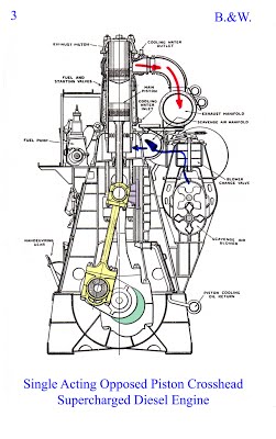
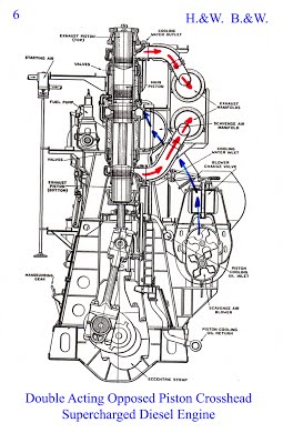
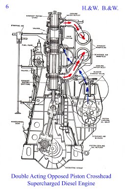
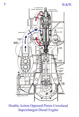
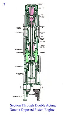
Following steam engine practice some manufactures made double-acting two-stroke and four-stroke diesel engines to increase power output, with combustion taking place on both sides of the piston, with two sets of valve gear and fuel injection.
While it produced large amounts of power and was very efficient The double-acting diesel engine's main problem was producing a good seal where the piston rod passed through the bottom of the lower combustion chamber, therefore no more were built.
By the 1930s superchargers were fitted to some engines. Crosshead bearings are still used to reduce the wear on the cylinders in large long-stroke marine engines which are nowadays fitted with turbochargers.
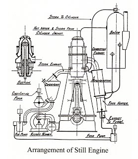
The still engine is a combined internal combustion and steam engine invented by W J Still.
It was designed to utilise a great proportion of the waste heat in the Engine Exhaust, which was lost as propulsion energy in ordinary gas or oil engines.
Taking a single cylinder of a marine type vertical engine working with oil, the upper part of the cylinder acts as an oil engine, the piston being impelled on its down stroke by the firing of the oil, while the lower part is a steam engine, the piston is driven by steam on its upward stroke.
The water jacket round the cylinder provides the steam which is generated by wild heat from the combustion space.
Scotts’ developed this concept and built two ships for the Ocean Steam Ship Co. fitted with Scott-Still Engines
M.V. Dolius 1924 and M.V. Eurybates 1928
M.V. Dolius was Sunk by U264 in May 1943
M.V. Eurybates engine was converted to straight diesel in July 1958
|
| |
| MEDIUM SPEED ENGINE | SHORT DESIGN FOR FERRIES | |
|
| |
| CIRCA 1930'S | ||
|
|
| CIRCA 30's/40's | CIRCA 50's |
| |
| 1950's |
J.G.Kincaid almost exclusively built Burmeister & Wain Engines while Scotts’ Engineering built Sulzer. Both Engines had Dry sumps and Turboblowers
the main differences being:-
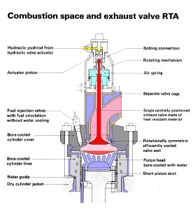
B.&W. Featured a poppet Exhaust Valve, Individual stand alone fuel pumps per Cylinder driven by a Camshaft just beneath the Top Platform, while SULZER used the piston with a long skirt. One Large Fuel Pump with drive from a Camshaft at middle platform level (Each Pair of cylinders supplied from a double timing block although each had a dedicated pump unit.)
Scotts’ built Doxford Opposed Piston Engines – The first being Eng. No. 715 in 1946 for China Navigation Co. - they turbocharged the first Doxford in 1957 for Elder Dempster’s M.V. Egori –and changed to manufacturing Sulzer in 1962 for M.V. Falaba again for Elder Dempster
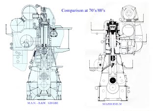
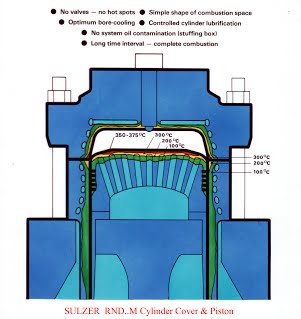
It should be noted , SULZER at this time made a virtue of having no Valves –however – (next slide)
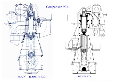
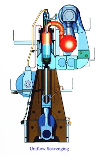
By the 90’s SULZER finally gave in – probably with encouragement from Mitsubishi, they also installed a poppet Exhaust Valve, went for uniflow scavenging and supplied their Fuel pumps in 2 block units – The Shipboard installations differed in the amount of Control and Monitoring supplied as standard The B.&W. systems were much simpler than their Sulzer Equivalents
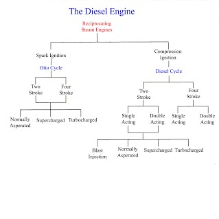
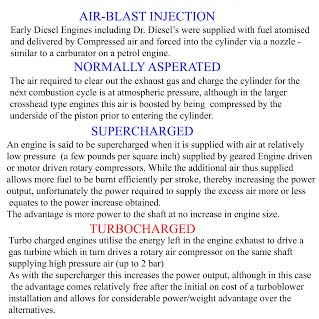
The example shown is a four stroke engine, similar to car engines, lower power traction engines , small generator and pump units. While heavier than an equivalent powered petrol engine, the diesel engine is much more fuel efficient. (up to 40%)
As of 2008, many common rail and unit injection systems already employ new injectors using stacked piezoelectric wafers in lieu of a solenoid, giving finer control of the injection event.
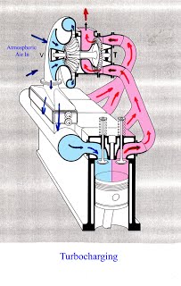
Variable geometry turbochargers have flexible vanes, which move and let more air into the engine depending on load. This technology increases both performance and fuel economy. Boost lag is reduced as turbo impeller inertia is compensated for.
Accelerometer pilot control (APC) uses an accelerometer to provide feedback on the engines level of noise and vibration and thus instruct the ECU to inject the minimum amount of fuel that will produce quiet combustion and still provide the required power (especially while idling).
The next generation of common rail diesels is expected to use variable injection geometry, which allows the amount of fuel injected to be varied over a wider range, and variable valve timing similar to that on gasoline engines.
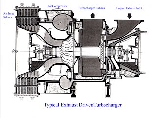
A two-stroke engine does not have an exhaust and intake stroke. These are performed when the piston is at the bottom of the cylinder. Therefore large two-stroke engines have a piston pump, or electrical driven turbo at startup. Smaller two stroke engines are fitted with turbochargers and a mechanically driven supercharger (i.e. a Roots blower).
Because turbocharged or supercharged engines produce more power for a given engine size as compared to naturally aspirated engines, attention must be paid to the mechanical design of components, lubrication, and cooling to handle the power.
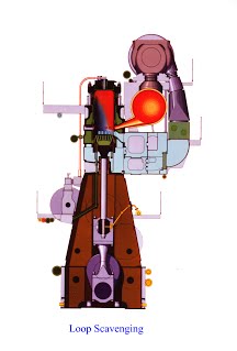
Often referred to as "Schnuerle" (or "Schniirl") loop scavenging after the German inventor of an early form in the mid 1920s, it became widely adopted in the 1930s and spread further afield after World War II. Loop scavenging is the most common type of scavenging used on modern two stroke engines.
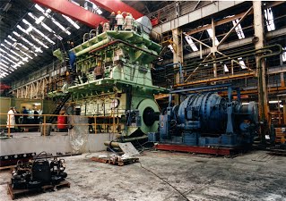
British Shipbuilders Slow Speed Engine Building, dwindled down to George Clark’s at Wallsend and John G. Kincaid at Greenock, combining to become Clark – Kincaid at Greenock with Britparts at Port-Glasgow handling spare parts supply.
This little engine building empire was eventually sold to H.L.D. Holdings for a token payment £ 3.00 by British Shipbuilders, Then H.L.D. Holdings in turn sold out to the Kaværner Group in 1990 for considerably more! The last move was supposed to improve the chances of the now Kaværner Kincaid company’s survival. - - - - Pass!
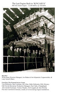
The last order for the Company was for four SULZER 6RTA62 Engines for Govan Shipbuilders, the final engine being C 519 this is the Last Slow Speed Diesel Engine to be built in the U.K. to date.
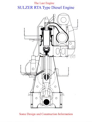
The Bedplate carries the Crankshaft.
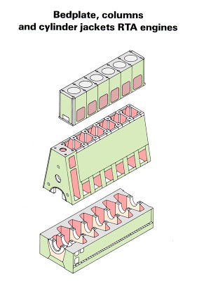
The Cylinder Block holds the Cylinder Liners, Pistons and Cylinder Covers.
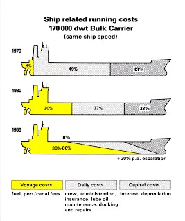
Oil Prices just kept increasing
Capital Costs decrease as Building Efficiency Improves
The wage bill has decreased as crews get smaller and smaller
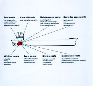
Crew Multi tasking - Deck Hand/ Engine room Ancillaries etc.
Maintenance costs are reducing because of better engine design, competition in the Spares market and of course Planned Maintenance getting the best out of the machinery.
